Wide Range Led Driver
I wanted to have LED’s in my Spyker KAT, but I want them directly to the battery and nospecial 5 V connections. The battery can be a 2S or a 3S (8.4 or 12.6 volts).
How to do that, in fact it is quite simple, make a constant current source. Looking in my college books I found the basic idea again. Two transisors and a few resitors should do the trick.Looking through my component bins I found a BC547 and 2N7000, two transitors sorted!
How to calculate the currnent: the BE voltage of the BC547 is about 0.6V the LED current is about 20mA given Ohms law (V=IR) R should be 30 Ohm.
I have red led’s at the back an white led’s on the front. The forward voltage of the red led is 1.8 volts and 3.3 volts for the white led.
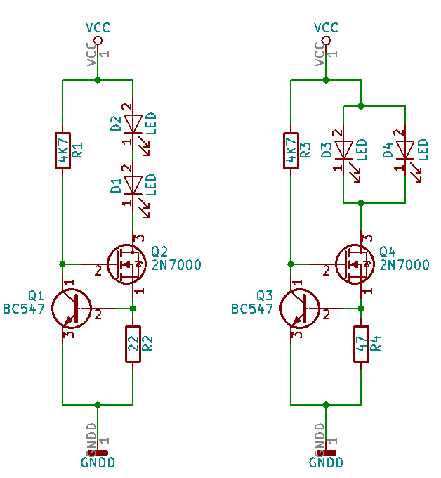
With a breadboard and the components and some experimentation I came up with the following resistors R1 and R3 are 4K7 Ohm (I just picked something to have a small current through the transistors, nothing special. The red leds D1 and D2 are placed in series. The total voltage over Q2 will be VCC-21.8-0.6 volt = VGSQ2. ID1andD2 = 0.6/22=27mA, the power dissipation 27mAVGSQ2. After running them for half an hour the LED’s and transistors were still at ambient temperature. D3 and D4 are white LED’s, the forward voltage of these is about 3.3V, so placing them in series would get me 6.6V. This is a possibility, but it will narrow the voltage range of this driver. Placing then in parallel will reduce it to 3.3V but double the current. Again playing with the brightness and keep an eye on the temperatures, I came to 47 Ohm for R4.
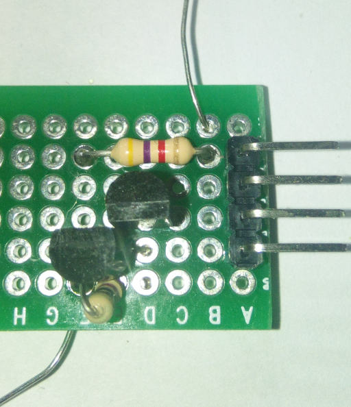
Making it real, placing all the components on a board and solder it. On the left is the component side. It could have been smaller, but this is good enough. Maybe a later version will be an smd one, but I guess later is going to be never.
The connections are:
- top wire Vcc
- bottom wire GND
On the left:
- top is anode
- cathode of led one
- anode
- cathode of led two
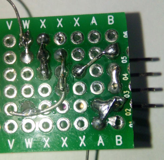
To make it easier for me for the next time I also added the solder side.
Next stop, make it controlable with an RC remote, still thinking about how. Discrete or with an Arduino.